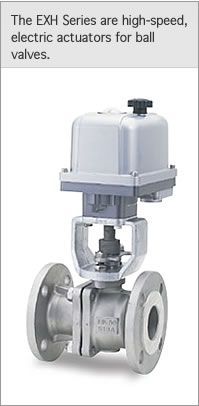
|
|
|
|
|
|
|
|
|
|
|
|
Actuator size
|
Type 1
|
Type 2
|
Type 3
|
Type 4
|
|
|
Model
|
EXH100-1
|
EXH200-1
|
EXH100-2
|
EXH200-2
|
EXH100-3
|
EXH200-3
|
EXH100-4
|
EXH200-4
|
|
|
Power supply
(single-phase, 50/60 Hz, AC)
|
100V±10%
|
200V±10%
|
100V±10%
|
200V±10%
|
100V±10%
|
200V±10%
|
100V±10%
|
200V±10%
|
|
|
Rated current∗1 (A)
|
0.65
|
0.35
|
0.65
|
0.35
|
1.2
|
0.6
|
2.8
|
1.5
|
|
|
Quarter-turn (90°)
opening / closing time∗2
|
50Hz (sec)
|
About 9
|
About 14
|
About 21
|
About 28
|
|
|
60Hz (sec)
|
About 8
|
About 12
|
About 17
|
About 23
|
|
|
Rated output torque (N¥m)
|
9.8
|
49
|
196
|
588
|
|
|
Motor output (W)
|
16
|
31
|
85
|
|
|
Motor power consumption (W)
|
65
|
120
|
280
|
270
|
|
|
Motor protection
|
Built-in thermal protector (120°C open)
|
|
|
Rotating direction
|
Open: counterclockwise, viewed from the top of the actuator
Closed: clockwise, viewed from the top of the actuator
|
|
|
Duty factor
|
30% ED or lower (at a room temperature of 20°C)
|
|
|
Position detecting limit SW∗3
|
2 Switches, each for open / closing positions (no-voltage contact SWs for stop and signals at fully-open and
fully-closed ends). Contact capacity: 250 VAC, 11 A (Resistance load)
|
|
|
Operating environment
|
Indoors and outdoors (Not submersible in water)
|
|
|
Waterproofing /
Explosion-proofing
|
Compliant with IP67
|
|
|
Space heater capacity (W)
|
10/15 (at 100V/200V)
|
20
|
|
|
Space heater consumption power (W)
|
2.5/2.9 (at 100/200V)
|
4
|
|
|
Ambient temperature (°C)
|
−10 ∼ 50
|
|
|
Insulation class
|
JIS C 4003 Class E
|
|
|
Insulation withstand voltage
|
1 min. at 1500 VAC or 1 sec at 1800 VAC
|
|
|
Insulation resistance
|
100 MΩ or higher when measured with a 500-VDC insulation tester
|
|
|
Mounting attitude
|
Upright or horizontal (cannot be mounted upside down)
|
|
|
Lubricant
|
Grease
|
|
|
Conduit connection
|
G1 / 2 x 1 end connection
|
|
|
Wire connection
|
Screw terminal block M3
|
|
|
Stopper
|
Open / closed end fixed mechanical stopper
|
|
|
Manual operation
|
Pull up and turn the round handle on the top of the cover. The built-in interlock switch cuts off the power supply
to the motor and space heater during manual operation.
|
|
|
Power return
|
Push the handle down
|
|
|
Connection flange
|
Conforming to ISO5211
|
|
|
Coating colors
|
Cover: metallic silver. Case: metallic dark gray. Handle: matte black.
|
|
|
Weight∗4 (kg)
|
About 4.4
|
About 7.3
|
About 12.3
|
|
∗1 At startup, a current as high as approximately ten times the rated current surges through the actuator. Allow a sufficient safety margin for any electrical device connected to the actuator.
∗2 The quarter-turn (90°) opening / closing time indicated above refers to a time when the actuator is not connected to any valve and is not under any load. There will be a 3 to 10% delay when the actuator is connected to a valve.
∗3 Specify auxiliary limit switches (gold contacts) if your equipment employs a microcurrent load of 50 mA or less.
∗4 Weight of the actuator when not connected to a valve.